
Paper Modelling: Terrain Modelling Example
Author:
Lutz Pietschker
Version: 2010-12-31
Paper Modelling
|
Home Page
|
Links
|
What's New
Meshing Muckle Flugga
Downloads:
-
The complete
SketchUp 7 model of Muckle Flugga lighthouse and rock
(ZIP, 600 kB)
Note 1: Use this model freely for your own private purposes, and create links to this page, but do not re-publish it or sell it. I'd be rather angry if you did.
Note 2: The Sketchup model will differ in details from the images shown below because I added some corrections after I built the check model.
-
Google Sketchup program download: See
Google Sketchup website
(available for MacOS and Windows)
You may be aware that any surface can be approximated by a surface built from triangle shapes. The smaller the triangles, the better the approximation between the actual and the "meshed" surface. This principle is used in engineering to split technical surface shapes (like sheet metal) into a "mesh" of triangles. On this approximated surface you can work with recursive algorithms to calculate the tensions and deformations that you get when applying force to the structure; the method is called FEM (Finite Element Method) because the complete surface is split into "finite", i.e. limited, elements. (Similar methods exist for 3D bodies, but they are of no interest here.)
The nice thing about meshing is that you can use it to model just any surface shape you want, with any precision you need. Fortunately, the precision needed in paper modelling is far less than what you need in FEM calculations, but nevertheless the calculations could become tedious. This page shows how to apply the method on a paper model, step by step, as I made the model. I put the algebra that may be necessary for a manual meshing process (and some more) onto
a dedicated page, but actually it is not needed to make a model. CAD (computer aided design) software does the job much faster and neater, and very good programs are available very cheap today- free, in fact.
A very nice and intuitive tool I found is Google Sketchup, a free polyeder-modelling system. With Sketchup you build your model line by line, plane by plane, with an accuracy that is amply enough for paper models. It would not be enough for most engineering work, which is why I would not call it a CAD system (neither does Google), but if you see the work others already did with the tool you could be fooled. The good thing is that Sketchup works very, very intuitively, and you can progress step by step towards very sophisticated work once you mastered the basics.
However, be warned that it is next to impossible to derive a correctly scaled printable output from the freeware version of the tool. To get that, you need the professional version that includes the "layout" tool, and this version comes at about EUR 381 (as of July 2009), which is more than I am prepared to spend for my hobby just now. But SketchUp certainly
is
addictive, so one day, maybe... maybe soon!
For the work described here I used Google SketchUp 7 (freeware edition, which means that I worked from unscaled JPEG exports instead of PDFs).
By the way: If you want to do serious work with SketchUp I can very much recommend the books by Bonnie Roskes (about $70 for the set of basic and advanced exercises as PDF books). They are comprehensive, accurate, fun to work with and, in my opinion, worth every cent. I note that her website changed recently, please google for her new web address.
Let's assume we want to design a paper model of the
Muckle Flugga
lighthouse
(aka
North Unst lighthouse, see also the
satellite image). This lighthouse certainly is most impressive if built together with the rocks it stands on, otherwise the architecture is not that special (though the location certainly is- it is the northernmost building of the British isles). Here are some impressions of what this lighthouse and the rocks it stands on look like:
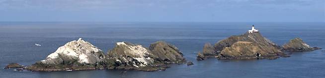
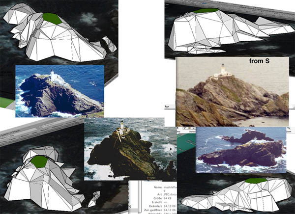
View of the complete group of rocks that lie before the coast Unst, one of the Shetland Islands.
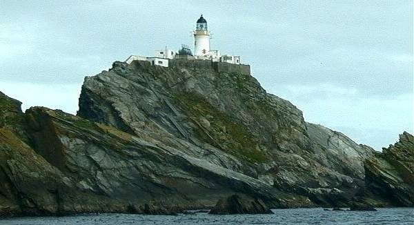
Impressive view from the water level, showing the slab-like structure of many rocks. The light's height above the water is given as 66 metres.
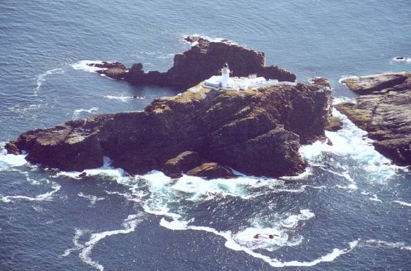
Good aerial view of the rock and the lighthouse
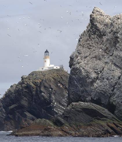
Again, a good view from the waterline, with more details of the lighthouse visible
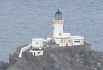
A smaller view that shows more details of the buildings... but I forget the page theme already. It is
not
about lighthouses.
I will use these images, Google Earth aerial views and some maps as my reference (the latter not included for copyright reasons). I work in a sequence of steps that are explained, one by one, below.
Please keep in mind that this page is about terrain modelling, so the focus is on modelling the rock, not the lighthouse itself.
I am no professional paper model designer, so there may be there are easier ways to perform certain steps- if you find a way to improve on the way I worked, please let me know!
Some lighthouse facts:
-
Position 60° 51.3’N, 00° 53.0’W (that's at the northern tip of the Shetland Islands)
-
Elevation 66 metres, nominal range 22 sm, Tower 21 metres high
-
Signal: Flashing (2) White every 20 secs
-
Established 1854, automated 1995
-
Design engineers: Thomas & David Stevenson
Decide What Will be the Main Contours
In this step I decide on the layout of the design, i.e. which planes and contours I need to have, which can be adapted if necessary, which details are the most important and which may be omitted.
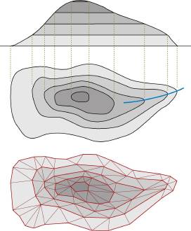 In many cases the easiest approach to this step will be to just copy the contour lines from a topographic map, decide on the most characteristic points, mark them on the contour lines and measure the X- and Y-co-ordinates. The big advantage of using contour lines is that all points on the same contour line have the same Z co-ordinate (=height), and the line on a map is even labelled with the actual height. This method can often be applied if the terrain is moderate, i.e. "hilly" rather than "rocky".
A more elegant way to obtain the contours would be to import an image of the map into a CAD system and draw the contours from the image, afterwards moving (elevating) the contours to their correct height.
Note that the example in the picture is just meant to illustrate the idea, it is not an example of a good terrain meshing. However, it shows some of the principles, for example that larger planar faces need not be split into triangles but can remain as polygons.
For some reasons, this approach does not work very well for the Muckle Flugga model:
-
The terrain is rocky, with some steep cliffs. Maps do not show reliable contour lines for such terrain.
-
We can show the characteristics of the rock better when we pick out the characteristic points and edges of the rock, as opposed to "arbitrary" triangulation.
-
Sheer and plain cliff faces allow us to model them in one piece rather than "meshing" them and breaking the face on the contour lines.
So I started with a few images found in the internet and an aerial view of the rocks. I identified the main contours in the pictures and marked them in the aerial view. By the way, I decided to use 1:1000 scale, and I did so for very practical reasons: The maximum base size was to be A4 (297x210 mm) because the model had to be transported (I was on holidays when I started this). I also decided to model just the actual lighthouse rock and, just for fun, one small rock immediately beside it, omitting the other rocks in its immediate vicinity.
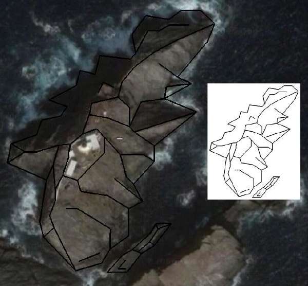
The characteristic contours as I saw them in the aerial image.
After that, I elevated the lines and faces to their correct height. I derived heights mainly from the photos (measured and estimated) with the main additional information being the height of 66 m given on the internet as the height of the light above the water.
Some of the contours and points already elevated to their correct height. The photos were always used to compare the impression given by them with what the model shows.
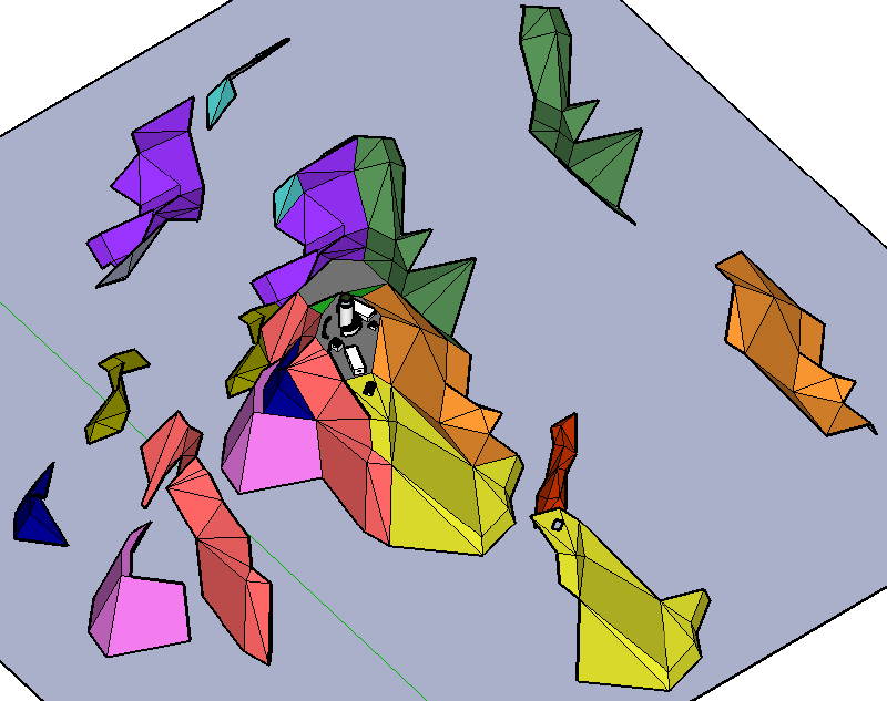
I now proceeded to add triangle surfaces to complete the model, and then simplified some nearly-planar surfaces into really planar ones to improve the impression of how the rock structure was captured (and to simplify the model, of course).
Interlude:
SketchUp makes it really simple to create planar surfaces.
-
Use the orbiter to view the intended plane sideways, to get an impression of how far the points actually "stick out" from the plane you want to use.
-
Re-define the axis system so that one of its co-ordinate planes (for example, the red-green X-Y-plane) is the intended model plane.
-
Move the points that stick out into this plane by moving them along the blue (Z) axis into this plane (fix the blue axis constraint by holding the shift key and pick the origin).
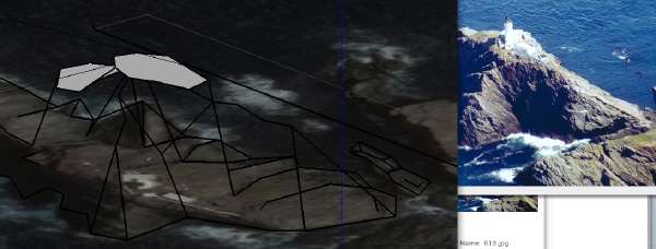
When I was done with the rock modelling, I checked result against the images again to see whether the characteristics of the landscape had been captured in the 3D model, and then applied some necessary corrections. This is the result that I got after a few iterations and that seemed good enough to me:
The SketchUp model and the photos compared
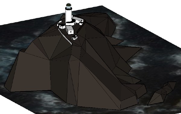
The SketchUp model, coloured and with buildings added (as I would add to to Google Warehouse, for example)
Decide on the Static Structure of the Design
We move to the paper model design now. In the first step I decide whether the paper model needs any additional internal structure to strengthen it and keep it in shape. Certain structures may also be needed just to make the model easier to assemble, or to create "tolerance buffers" that help to hide small mistakes you inevitably make while assembling the model.
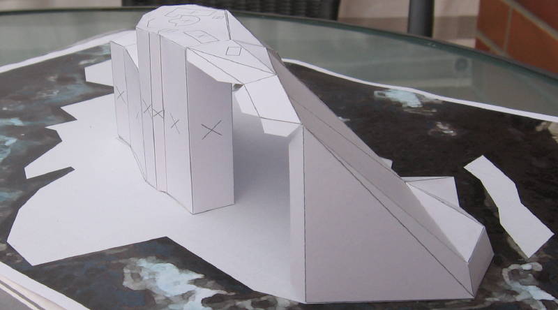
For this model things are not very complicated. I decide to use a column-like base structure for the lighthouse platform polyeder and to attach the cliff sides to this pillar. This should be enough to get the necessary structural strength for this small model.
(Note: Later I added some more internal structures to make assembly easier.)
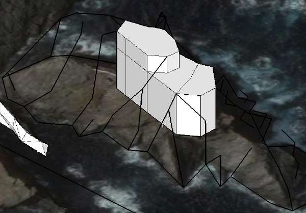
The basic columns that will give the model its static structure
Calculate the Point Co-Ordinates and Line Lengths
If you do not use a CAD system you need to calculate the line lengths from the point co-ordinates and then transfer them to the drawing board. CAD makes this step obsolete. Ah, the wonders of 3D graphics technology!
Disassemble the Polyeders and Triangles From the Structure
Now we must decide which surfaces will form the individual pieces of the assembly, i.e. where the cuts and the fold lines will go. Working with 3D CAD means that we can just select the faces we want to keep together on the model sheet, copy them, and unfold them step by step into the drawing surface (I used the X-Y-plane, i.e. top view). I did all the unfolding manually, but there are some plug-in programs available for Sketchup that assist you in the task.
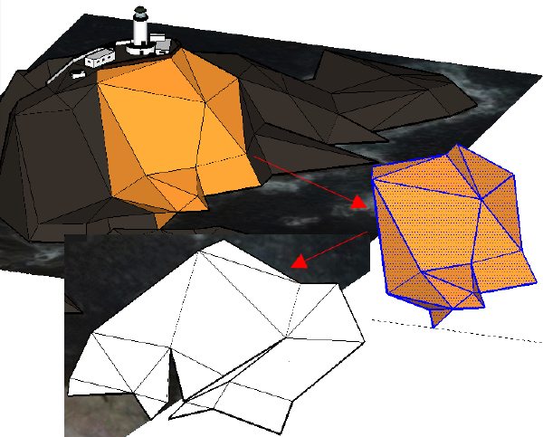
Part of the triangulated rock copied and unfolded into the X-Y plane
The problem here is to choose the sections in a way that there are no overlapping faces after unfolding them- you can't overlap your cardboard when printing, after all. Otherwise this is a straightforward, creative, if sometimes tedious process. If overlapping occurs there are two ways out of it: Reconsider which faces you keep together, or split the section, adding one more assembly step for the model builder.
You can add glue tabs now or later, as you wish (I did it later and improvised them for the check build). The glue tabs will probably have to be corrected later anyway, so maybe it is best to do them after the print sheets have been assembled and scaled to print size, and after your first test model has been built. I marked the rock sections with different colours before "exploding" the model; this helped a lot to see what was what, even a few hours after the work was done. I also used the colours as a reference for glue tabs.
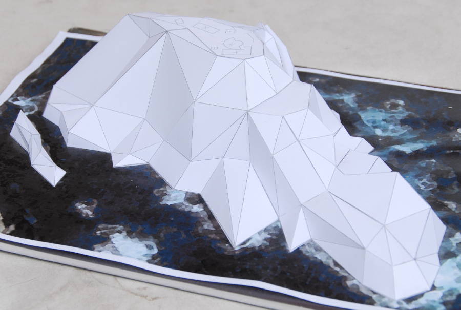
The rock sections colour-marked and exploded, waiting to be unfolded.
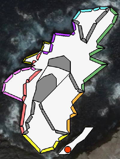
The places where the different rock sections will be placed. Some (gray) auxiliary Structures have been added, but they were not used in the test model.
And now comes the part that was more difficult than I expected: Creating scaled, printable sheets with correct glue tabs and an intelligent sheet layout. Something always seemed to go wrong. Which is precisely one of the reasons why you build a test model.
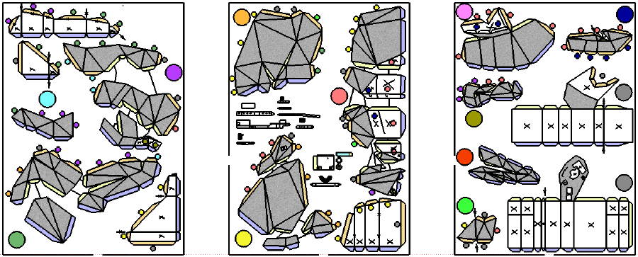
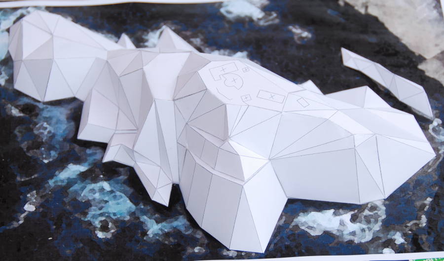
The print sheets in a somewhat-final version. Glue tabs are colour-coded (blue goes to base, buff to other parts of the model- see attached colour code blob to see to which). "X" surfaces will be invisible in the finished model.
Freeware SketchUp does not support precisely scaled output (only the Pro version does), so I had to improvise with JPEG exports of the sheets. This works well if you create all JPEGs from the same zoom factor, in one session, but it is next to impossible to re-export a sheet in exactly the same size. I imported the JPEGs into Macromedia Freehand (alas, a very dead tool by now) and printed from there.
Sketchup has very nice features to add colour or photo-quality textures to your model, but photo matches will not survive unfolding the model. Since the Pro version lets you export into formats for professional graphics design programs, such programs may be the better choice of tool if you go for a real print edition.
Assemble the model to check your work
The moment of truth. Does this work as I imagined it? Do I have access to all the gluing tabs, and do the tabs fit to where they are supposed to go? Do the unavoidable tolerances build up to huge gaps, or can I hide them in the section boundaries? Here are some images of the progress of my "white model". I did this in my holiday hotel room, without a proper toolset, and the model was printed on very flimsy paper (80 or 100 g/m2, I believe, i.e. ordinary all-purpose printer paper). Still, it worked.
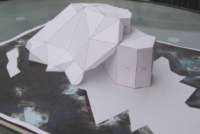
The central "column"with the first rock sections attached. The "X" faces will be hidden by other parts of the model. The base sheet is a photoshopped aerial image, overlaid with the rock base contour.
Same building stage, other view. Note the building contours on the top platform.
The next images are after completion of the rock structure. The moment of suspense came, of course, when fitting the last part. Can you guess which one that was?
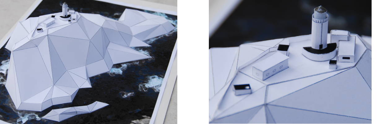
The view from the South-East
The North face of the rock; the complete future building arrangement is in view.
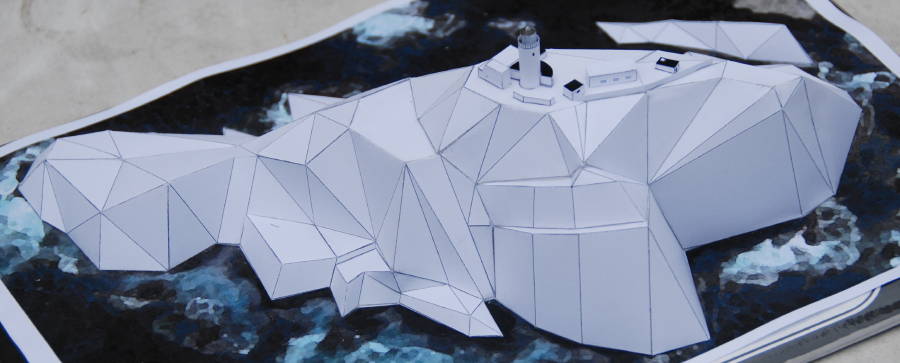
North-East view with buildings in place
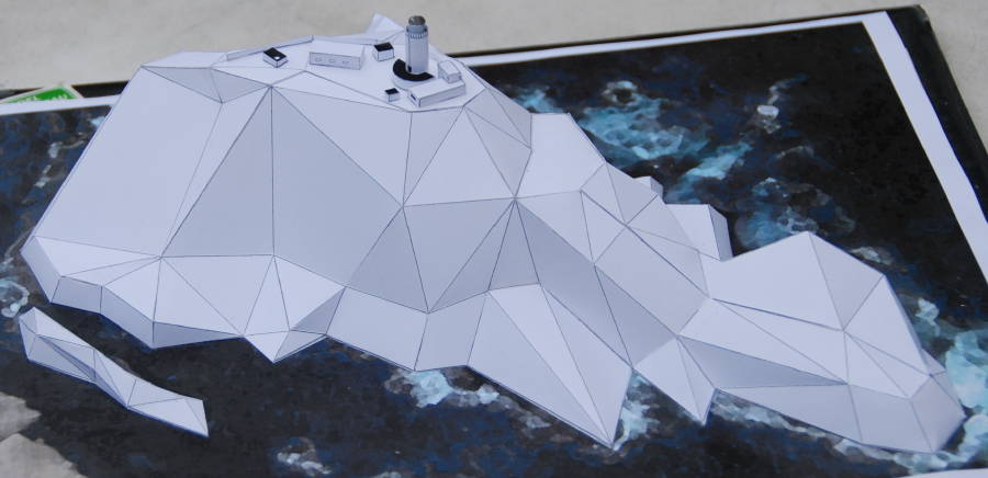
Same model, seen from the South-East side
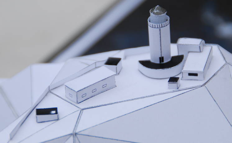
The buildings in a close-up view. Well, you cannot expect too much detail at this scale (1:1000, the lighthouse itself is about 18 mm high from plateau base to top).
If you encounter problems, you need to go back to the 3D modelling or the print sheets and to correct things that do not fit; I was lucky to have no problems that I could not fix without resorting to new prints.
The white "check" model is finished now. For publishing work, this would be the time to go back to the design board and apply colours, textures and more detail. The final step before actually publishing the model would be to prepare the final print sheets, which is a major task in itself if you need to achieve professional results. I can not give a lot of advice for that kind of work.
Finally, two pictures showing the same views, once from the Sketchup virtual model and once from the finished white model:
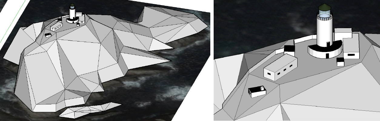
The virtual rock and plateau
The white model of same. Similarities are by no means unintended.
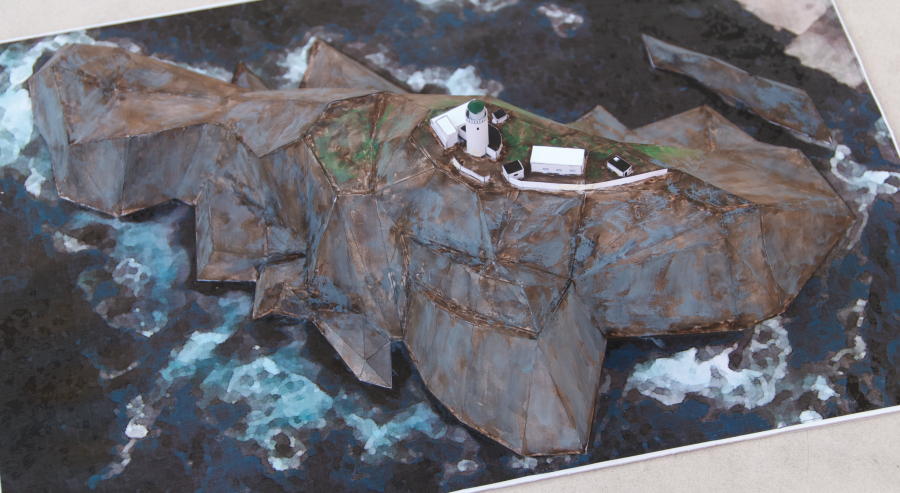
The Result
When I was done, I found the result to pretty to throw away, so I proceeded to colour the surfaces. I wanted to concentrate on the terrain-building technique here, so I just painted the completed model instead of adding texture and colour to the print sheets and doing it all again. I used water colours, and as you can see I am no expert in this. Doing it with bad brushes (no good ones to have where I worked) did not help, either. And of course there is the problem of what colour those rocks really have; the pictures I had differed considerably, and I had to decide on some compromise.
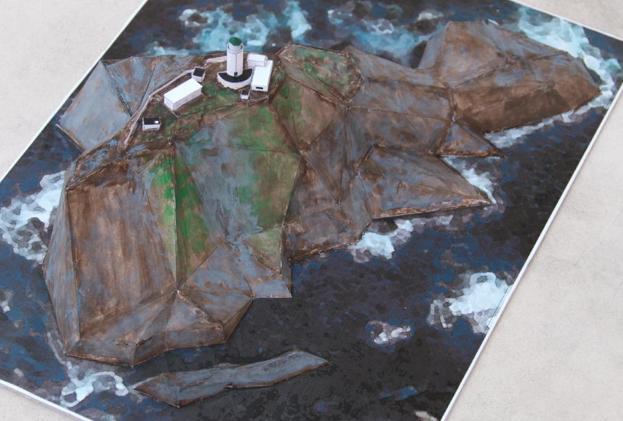
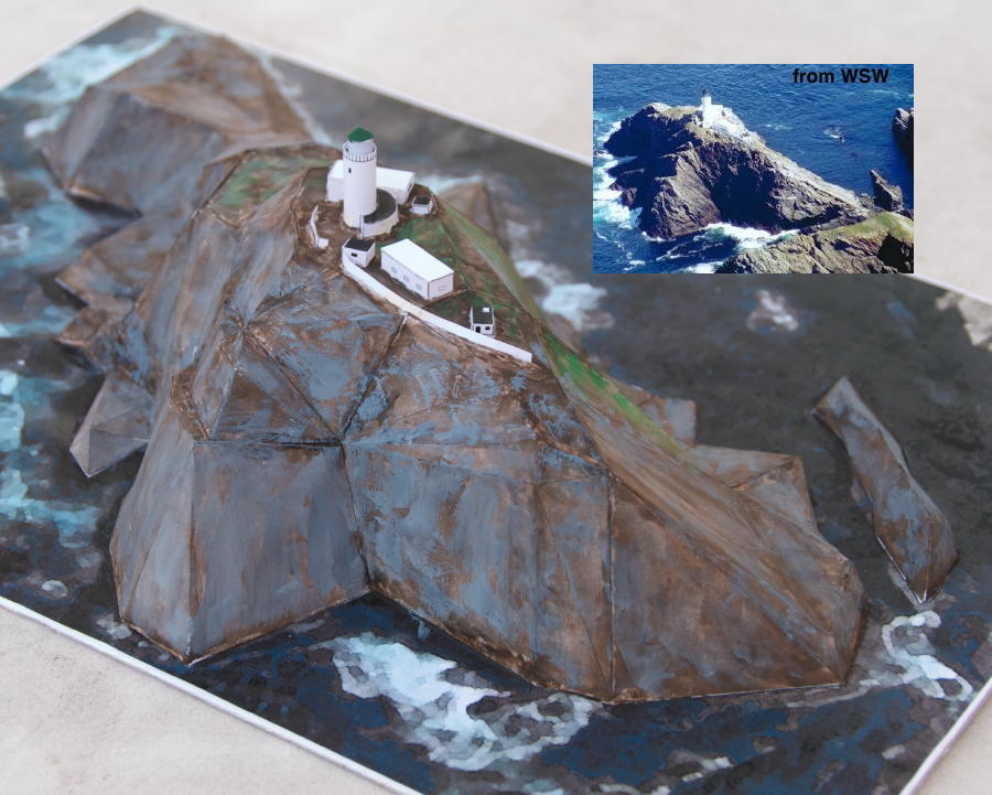
The South-East side with the small companion rock. This is the only side that shows some green on some of the pictures.
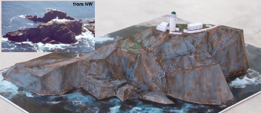
North-Western view, the side looking out to the open sea
The big cliffs on the South-Western tip of the rock
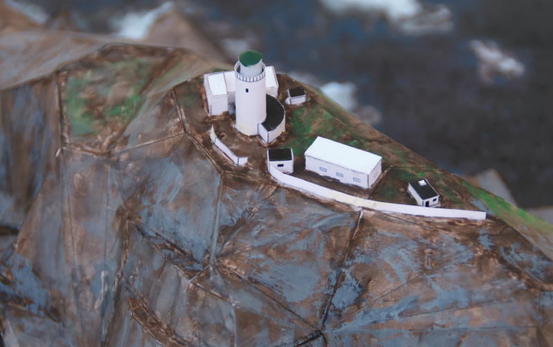
Closer view on the buildings. In fact they had to be reinforced after the initial construction because during winter gales the waves swept the plateau and damaged walls and buildings. It must have been a frightful experience for the lighthouse wardens!
Last but not least, a comparison again between the finished model and the original images I worked from:
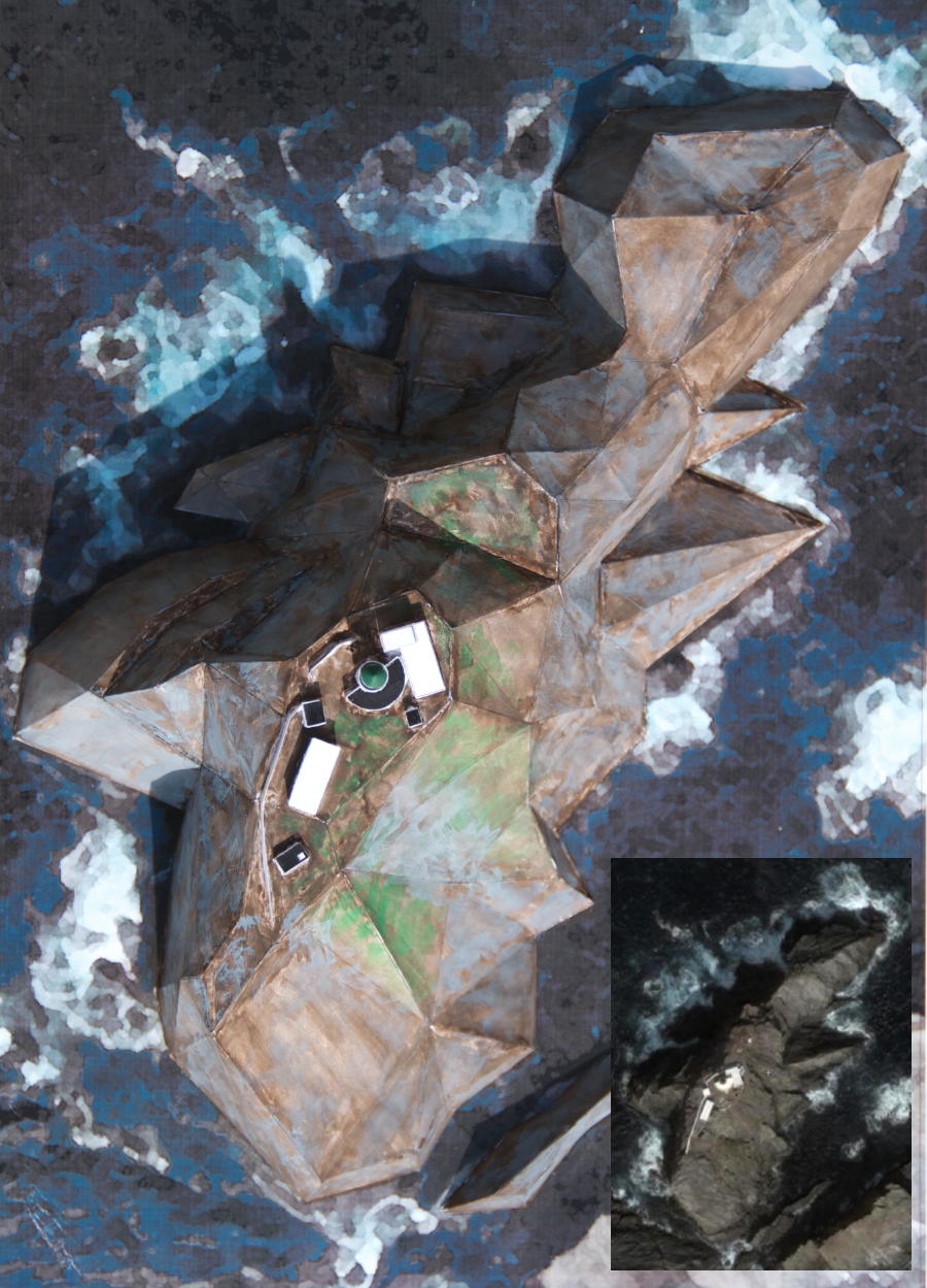
The aerial view, compared to the Google Earth image
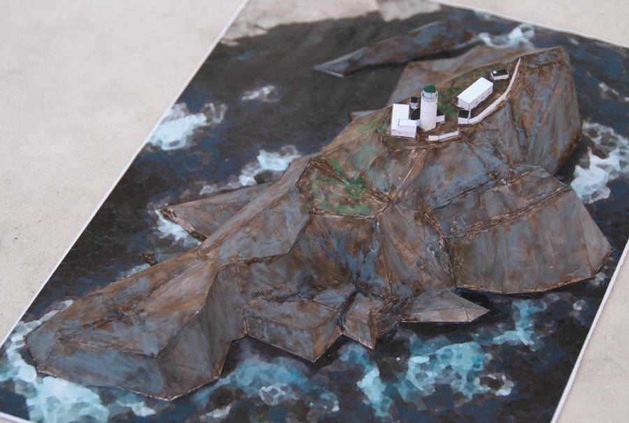
The big rocks on the West-South-Western side
The complete rock from the sea side. The image background shows an adjacent rock I did not include in the model.
Well, that's it! All in all, I did worse. Have fun with your own models, and if you decide to build Muckle Flugga, by all means tell me about your experience.
As the author of this page I take no expressed or implied responsibility for the content of external links; opinions expressed on such pages are not necessarily mine. The web space provider is not responsible for the contents of this page or any linked pages.


Written and published by Lutz Pietschker. Please send comments about technical problems to the
site master.
-Made with a Mac!-
, last change
2011-03-12