 Point-to-Point Vectors, Planes
Author:
Lutz Pietschker
Version: 2010-12-31
Paper Modelling | Home Page | Links | What's New
This section compiles some formulae I needed to look up when modelling, under the assumption that if I had to look them up others will need to do so as well, and the page may save them some time. The description is made only as far as necessary to understand the use of the algebra in paper modelling, there is no attempt to explain things further. The algebra may even be useful if you use a CAD system for the actual modelling, because it clarifies some of the principles used.
Vector algebra is very well suited for many mathematical problems encountered in paper modelling. If you forgot some of it, this section may be useful.
In many calculations checks are made whether a certain value "is equal to zero". Zero is a mathematical concept, not one of the physical world, so please translate all such checks into "is near enough to zero that the difference does not matter". The "allowed difference" is usually called epsilon. How near "near enough" is, i.e. the value for epsilon must be decided upon on any specific case. For example, if you design a castle that will have a model size of 80 by 40 cm you may decide that epsilon is 0.1 mm, i.e. points calculated to be 0.1 mm apart would be considered to be the same point, or points that delimit a plane and that are calculated to be 0.1 mm off the mathematically-ideal plane are still considered to be coplanar with the rest of the points (depending on the scale you use, your epsilon may even be bigger). Please keep this in mind should you go ahead and program your own tools for paper model design!
By the way, the epsilon could be applied to the co-ordinates and values in either "nature" (i.e. the original structure) or the model (i.e. the scaled structure). Applying it to the model seems to be the better solution because you can check it directly against the precision you want to achieve. However, be aware that when you re-scale the model the tolerance in model co-ordinates may translate to a tolerance in nature that is different from what you originally intended, so it is a good idea to do the backward calculation of epsilon from model to nature. For example, if you have a 1:250 scale model an decide that tolerances of 0.1 mm do not matter this means that tolerances in nature of 0.1x250 =25 mm do not concern you (which seems to be very reasonable).
For many model designs tolerances of 0.1 mm and of 2 degrees are actually good values that leave room for calculation (rounding) errors of your tool and are small enough to be of no concern in the construction. Or, to use another approach, since you seldom calculate measurements to more than 3 digits any tolerance in the 4th or fifth digit could be ignored, so an epsilon of 1/1000 or 1/10000 of the maximum dimension of the model may be a good rule of thumb that does not over-tax the capabilities of calculating tools.
Point-to-Point Vectors, Planes
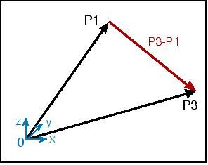
Every design needs a point of origin. The co-ordinates (x,y,z) of the points can be interpreted as vectors from the origin to the point (a.k.a location vectors). A line L from point A to point B can be described as
L
=
B
-
A
or
L
= (xB-xA, yB-yA, zB-zA)
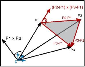
In the example to the right, the red vector is defined as
P3 - P1 = ( x3-x1, y3-y1, z3-z1 )
 Note that three points that are
not
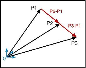
on the same straight line define a 3D plane, which means that two vectors originating from the same point also define a plane (if they are not collinear, see example to the right). In the example below,
P1
and
P3
define a plane that goes through the co-ordinate origin, while (P2-P1) and (P3-P1) (or (P3-P2) define a plane that contains the three points
P1,
P2,
P3.
Note that three points that are
not
on the same straight line define a 3D plane, which means that two vectors originating from the same point also define a plane (if they are not collinear, see example to the right). In the example below,
P1
and
P3
define a plane that goes through the co-ordinate origin, while (P2-P1) and (P3-P1) (or (P3-P2) define a plane that contains the three points
P1,
P2,
P3.
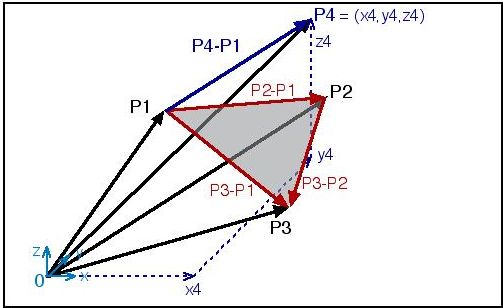
The image below shows a constellation of points and vectors that is often encountered in paper modelling tasks: 3 points are given (P1, P2, P3), as the defining points of a triangle, in Cartesian co-ordinates or "location vectors". We need the lengths of the triangle sides. We also have a fourth point P4 that we need to relate to the triangle.
The length of a vector A is
length = SQRT( (xA+yA+zA)2 )
If P1 and P3 are the start and end points of a vector, its length is
length = SQRT( (x3-x1)2 + (y3-y1)2 + (z3-z1)2 )
If you need a vector of some specific length b, and your original vector has the length a, you get a vector of the desired length as
A = ( xA*b/a , yA*b/a , zA*b/a )
 Orthogonality Check and Angle (Scalar Product)
The scalar product of two vectors A and B is written as A*B and can be calculated as
a = xA*xB + yA*yB +zA*zB
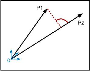
Note that the result is a single number, not a vector. The cosine of the angle between two vectors can be calculated as their scalar product divided by their lengths, which means that the angle is
alpha = arc cos( (A*B) / (length(A) * length(B)) )
You see from the diagram that part of the scalar product is the projection of one vector onto the other. If the scalar product of two vectors is 0 (zero) the vectors are orthogonal two each other, i.e. the angle in space between them is 90 degrees, which means in terms of geometry that the projection has the length 0.
 Parallelity/Collinearity Check, Orthogonal Line (Vector Product)
The result of the "vector product" of two (non-parallel) vectors is a new vector that is orthogonal to both of them. The vector product is written as AxB and evaluates to a new vector (hence the name):
AxB = (yA*zB - zA*yB) , (zA*xB - xA*zB) , (xA*yB - yA*xB)
The fact that the new vector is orthogonal to both of the original vector can be used to construct a line that is orthogonal to a triangle (like the vector (P2-P1) x (P3-P1) in the diagram).
The vector product can be used to check whether two vectors are parallel (collinear): If the result of the vector product is a "zero vector", i.e. the vector (0,0,0), the original vectors are parallel.
There is another check for collinearity: If two vectors are collinear, one can be expressed as a multiple of the other:
A
= b *
B
or
xA
= b * xB, yA
= b * yB, zA
= b * zB
(note that b is negative if the vectors point into opposite directions)
To check for collinearity, calculate b from the x values and check whether both the y and z co-ordinate condition are true (inside the limits of precision, see above). If they are, the vectors are collinear.
A sequence of vector and scalar product allows us to calculate whether a given point is in a given plane and if not, what the shortest distance from the point to the plane is. We work with three vectors that originate from the same point (this is important because otherwise we get results that are mathematically correct but misleading from a model designer's point of view). Vectors A = (P2-P1) and B = (P3-P1) define a plane, for example they could be two sides of a triangular plane of the model.
P4 defines the point we want to check.
First we calculate
C
=
A
x
B
(see formula above). Then we calculate the scalar product between
C
and
P
(a =
C
*
P, see formula given above). If a=0, the point
P
is in the plane defined by
A
and
B.
(Note: If the start point of
P
was different from that of
A
and
B
all this check would tell us was whether
P
was
parallel
to
A
and
B.)
If we want to know exactly how far the point is from the plane (i.e. its shortest distance d from the plane) we need to go one additional step:
d = a / length( C )
Another check can be made for co-planarity: If a point P4 is in the plane defined by vectors A and B, it must be possible to define
P4
= a *
A
+ b *
B
or
xP4
= a*xA+ b*xB, yP4
= a*yA
+ b*yB, zP4
= a*zA
+ b*zB
This is a system of 3 linear equations with 2 unknown values (a, b). Thus, we can solve the first two equation to get
b = (yP4
- (xP4*yA/xA)) / (yB
- (xB*yA/xA))
a = (xP4/xA) - (b*xB/xA)
and then check whether the third equation (for z) is true (inside the precision limits). If it is, the point P4 is in the plane defined by A and B.
The "linear equation" coplanarity check can also be used to get the z co-ordinate of a point P4 of which we know x and y, but want to get such a z that P4 is in the plane defined by A and B. What we need to do is to calculate b and a as above (this can be done because xP4 and yP4 are known), and then get z through the third equation:
zP4 = a*zA + b*zB
Note: This is a common problem if we get the x and y co-ordinates of the points from a floor plan (or ground plan, or map) but need to fit certain points into given 3D planes. It can also be used to combine two adjacent triangles that are nearly coplanar into one (plane) polygon by re-calculating the z value of one of the points that are not common to the triangles.
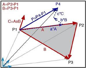 Projection into a Plane
This calculation is also often needed when we want to simplify a model construction by combining adjacent, nearly-coplanar triangles into one plane polygon. To do so we need to project all non-coplanar points of the polygon into the plane of the reference plane, defined by the triangle P1, P2, P3.
The usual representation of a point in space is in "Cartesian co-ordinates", i.e. the orthogonal x,y,z-system. But a point can be represented in any co-ordinate system, for example in the (usually) non-orthogonal system created by the vectors that define a plane. P4 can be written as
P4 = P1 + ( a*A + b*B + c*C )
,i.e. in a "parametric" form that refers to the given vectors
A,
B
and
C. This vector equation can be transformed into a set of three linear equations (one each for x, y, z) that allows us to calculate the unknown values of a, b and c. By setting c=0 we get the projection point.
However, this is tedious work (if not "mechanised" by a calculation sheet), and fortunately there is a method that suits our purpose and that is easier to handle.
However, there is an easier way, given the information we gathered above, in the "coplanarity check" section: We just need to get the distance d of P4 from the plane, and then move P4 parallel to C by that distance. This means that the new (projected) point P' is calculated as
P4'
=
P4
- (
C
*(d / length(C) ) )
or
xP4'
= xP4
- ( xC
* d / length(C) )
yP4'
= yP4
- ( yC
* d / length(C) )
zP4'
= zP4
- ( zC
* d / length(C) )
Note that a projection into a plane that is not parallel to the x-y, x-z or y-z plane changes all three co-ordinates of the point.
Apart from simple geometric constructs, most of these have to do with the "unfolding" of three-dimensional shapes into a plane (paper) surface. A very useful source for unfolding (or unrolling) techniques are older engineering books that describe graphical unfolding techniques for various shapes for sheet metal design.
Abbreviations:
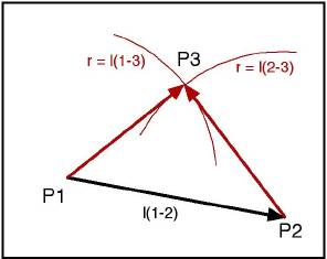 Triangle Construction
If you have the lengths of the three sides of a triangle, the triangle is constructed by drawing one of the lines and drawing two arcs around the end points with a pair of compasses, one each with the length of the other sides. The point of intersection is the third point of the triangle.
Some useful formulae for triangles:
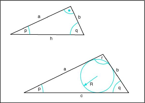
Plane Rectangular Triangle:
If the angle between a and b is = 90 degrees, then
Any Plane Triangle:
| Use | Formulae | Remarks |
|---|---|---|
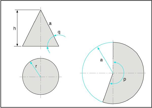
| General |
diameter d = 2 * r
cone circumference c = PI * 2 * r cone circumference c = PI * d side a = SQRT( r2 + h2 ) angle q = arctan( h/r ) angle q = arcsin( h/a ) angle q = arccos( r/a ) angle p = 360 * r / a |
|
| r, h given |
a = SQRT( r2
+ h2
)
p = 360 * r / a |
(we need a and p) |
| r, q given |
h = r * tan(q)
a = SQRT( r2 + h2 ) p = 360 * r / a |
(we need a and p) |
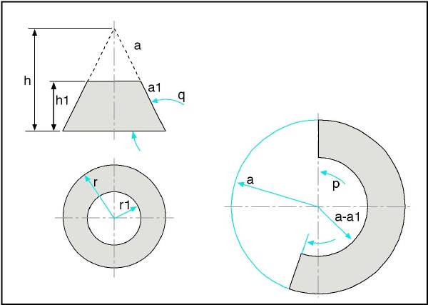
| Use | Formulae | Remarks |
|---|---|---|
| General | r / r1 = a / a1 = h / h1 | see above for basic calculations |
| if r1 / a1 / h1 given | calculate r, a, h and continue as above |
| Use | Formulae | Remarks |
|---|---|---|
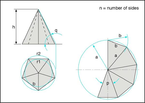
| General |
side a = SQRT( r22
+ h2
)
h = SQRT( a2 - r22 ) r2 = SQRT( a2 - h2 ) r1 = r2 * cos( 180/n ) b = 2 * r2 * sin( 180/n ) b = 2 * r1 * tan( 180/n ) angle q = arctan( h/r1 ) angle q = arcsin( h/a ) angle q = arccos( r1/a ) angle p = 2 * arcsin( b/(2*a) ) |
Obviously, n must always be assumed to be given |
| regular 6-sided pyramid | r2 = b | |
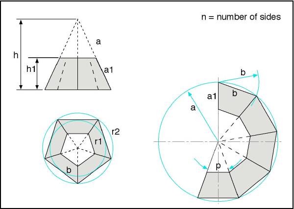
| h, q given |
a = h / sin( q )
b = 2 * r1 * tan( 180/n ) p = 2 * arcsin( b/(2*a) ) |
(we need a and b, or a and p) |
| r1, h given |
r2 = r1 / cos( 180/n )
a = SQRT( r22 + h2 ) b = 2 * r1 * tan( 180/n ) p = 2 * arcsin( b/(2*a) ) |
(we need a and b, or a and p) |
| r2, h given |
a = SQRT( r22
+ h2
)
b = 2 * r2 * sin( 180/n ) p = 2 * arcsin( b/(2*a) ) |
(we need a and b, or a and p) |
| Use | Formulae | Remarks |
|---|---|---|
| General |
a / a1 = h / h1
(inner and outer radii at bottom/top of fulcrum have the same relation) |
see above for basic calculations |
| if a1 / h1 given | calculate a, h and continue as above |
As the author of this page I take no expressed or implied responsibility for the content of external links; opinions expressed on such pages are not necessarily mine. The web space provider is not responsible for the contents of this page or any linked pages.
Written and published by Lutz Pietschker. Please send comments about technical problems to the
site master.
-Made with a Mac!-
, last change 2011-03-12